Internet Multicast Today
by Mark Handley, ACIRI and Jon Crowcroft ,
University College London
When you need to send data to many receivers simultaneously, you have two options: repeated transmission and broadcast. Repeated transmission may be acceptable if the cost is low enough and delivery can be spread out over time, as with junk mail or electronic mailing lists. Otherwise, a broadcast solution is required. With real-time multimedia, repeated delivery is feasible, but only at great expense to the sender, who must invest in large amounts of bandwidth. Similarly, traditional broadcast channels have been very expensive if they cover significant numbers of recipients or large geographic areas. However, the Internet offers an alternative solution: IP multicast effectively turns the Internet into a broadcast channel, but one that anyone can send to without having to spend huge amounts of money on transmitters and government licenses. It provides efficient, timely, and global many-to-many distribution of data, and as such may become the broadcast medium of choice in the future.
The Internet is a datagram network, meaning that anyone can send a packet to a destination without having to reestablish a path. Of course, the boxes along the way must have either precomputed a set of paths, or they must be relatively fast at calculating one as needed, and typically, the former approach is used. However, the sending host need not be aware of or participate in the complex route calculation; nor does it need to take part in a complex signaling or call setup protocol. It simply addresses the packet to the right place, and sends it. This procedure may be a more complex procedure if the sending or receiving systems need more than the default performance that a path or network might offer, but it is the default model.
Adding multicast to the Internet does not alter the basic model. A sending host can still simply send, but now there is a new form of address, the multicast or host group address. Unlike unicast addresses, hosts can dynamically subscribe to multicast addresses and by so doing cause multicast traffic to be delivered to them. Thus the IP multicast service model can be summarized:
- Senders send to a multicast address
- Receivers express an interest in a multicast address
- Routers conspire to deliver traffic from the senders to the receivers
Sending multicast traffic is no different from sending unicast traffic except that the destination address is slightly special. However, to receive multicast traffic, an interested host must tell its local router that it is interested in a particular multicast group address; the host accomplishes this task by using the Internet Group Management Protocol (IGMP).
Point-to-multipoint communication is nothing new. We are all used to the idea of broadcast TV and radio, where a shared medium (the radio frequency [RF] spectrum) is partitioned among users (transmitter or TV/ radio station owners). It is a matter of regulation that there is typically only one unique sender of particular content on any given frequency, although other parts of the RF spectrum are given over to free use for multiparty communication (police radio, citizen band radio, and so on).
The Internet multicast model [3] is very similar. The idea is to convert the mesh wide-area network that is the Internet (whether the public Internet, a private enterprise net, or intranet makes no difference to the model), into a shared resource for senders to send to multiple participants, or groups.
To make this group communication work for large-scale systems in the sense of a large number of recipients for a particular group, or in the sense of a large number of senders to a large number of recipients, or in the sense of a large number of different groups it is necessary, both for senders and for the routing functions to support delivery, to have a system that can be largely independent of the particular recipients at any one time. In other words, just as a TV or radio station does not know who is listening when, an Internet multicast sender does not know who might receive packets it sends. If this scenario sends out alarm bells about security, it shouldn't. A unicast sender has no assurance about who receives its packets either. Assurances about disclosure (privacy) and authenticity of sender/recipient are largely separate matters from simple packet delivery models. Security is a topic of much research and the focus for the recently formed Internet Research Task Force (IRTF) research group, Secure Multicast Group (SMuG).
The Internet multicast model is an extension of the datagram model; it uses the fact that the datagram is a self-contained communications unit that not only conveys data from source to destination, but also conveys the source and destination address information. In other words, in some senses, datagrams signal their own path, both with a source and a destination address in every packet.
By adding a range of addresses dedicated for sending to groups, and providing independence between the address allocation and the rights to send to a group, the analogy between RF spectrum and the Internet multicast space is maintained. Some mechanism, as yet unspecified, is used to dynamically choose which address to send to. Suffice it to say that for now, the idea is that somehow, elsewhere, the address used for a multicast session or group communication activity is chosen so that it does not clash with other uses or users, and is advertised to potential senders and receivers.
Unlike the RF spectrum, an IP packet to be multicast carries a unique source identifier, in that such packets are sent with the normal unicast IP address of the interface of the sending host.
It is also worth noting that an address that is being used to signify a group of entities must surely be a logical address (or in some senses a name) rather than a topological or topographical identifier. We shall see that this means there must be some service that maps such a logical identifier to a specific set of locations in the same way that a local unicast address must be mapped (or bound) to a specific location. In the multicast case, this mapping is distributed. Note also that multicast Internet addresses are in some sense "host group" addresses, in that they indicate a set of hosts to deliver to. In the Internet model, there is a further level of multiplexing, that of transport level ports, and there is room for some overlap of functionality, since a host may receive packets sent to multiple multicast addresses on the same port, or multiple ports on the same multicast address.
This model raises numerous questions about address and group management, such as how these addresses are allocated. The area requiring most change, though, is in the domain of the routing. Somehow the routers must be able to build a distribution tree from the senders to all the receivers for each multicast group. The senders don't know who the receivers are (they just send their data), and the receivers don't know who the senders are (they just ask for traffic destined for the group address), so the routers have to do something without help from the hosts. We will examine this scenario in detail in the section "Multicast Routing."
Roadmap
The functions that provide the Standard Internet Multicast Service can be separated into host and network components. The interface between these components is provided by IP multicast addressing and IGMP group membership functions, as well as standard IP packet transmission and reception. The network functions are principally concerned with multicast routing, while host functions also include higher-layer tasks such as the addition of reliability facilities in a transport-layer protocol. That's the order in which we cover each of these functions in the rest of this article. At the end of the article we list the current status of Internet Engineering Task Force (IETF) specification for the various components.
Host Functions
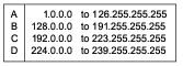
As we stated above, host functionality is extended through the use of the IGMP protocol. Hosts and routers, which we will look at later, must be able to deal with new forms of addresses. When IP Version 4 addressing was first designed, it was divided into classes as shown in Figure 1.
Figure 1: Internet Address Classes
*Note:Click above for larger view
Originally Class A was intended for large networks, B for midsize networks, and C for small networks. Class D was later allocated for multicast addresses. Since then, classless addressing has been introduced to solve Internet scaling problems, and the rules for Classes A, B, and C no longer hold, but Class D is still reserved for multicast, so all IPv4 multicast addresses start with the high-order 4-bit "nibble": 1110
In other words, from the 2 32 possible addresses, 2 28 are multicast, meaning that there can be up to about 270 million different groups, each with as many senders as can get unicast addresses! This number is many orders of magnitude more than the RF spectrum allows for typical analog frequency allocations.
For a host to support multicast, the host service interface to IP must be extended in three ways:
- A host must be able to join a group, meaning that it must be able to reprogram its network level, and possibly, consequentially, the lower levels, to be able to receive packets addressed to multicast group addresses.
- An application that has joined a multicast group and then sends to that group must be able to select whether it wants the host to loop-back the packets it sent so that it receives its own packets.
- A host should be able to limit the scope with which multicast messages are sent. The Internet Protocol contains a Time-To-Live (TTL) field, used originally to limit the lifetime of packets on the network, both for safety of upper layers, and for prevention of traffic overload during temporary routing loops. It is used in multicast to limit how "far" a packet can go from the source. We will see below how scoping can interact with routing.
When an application tells the host networking software to join a group, the host software checks to see if the host is a member of the group. If not, it makes a note of the fact, and sends out an IGMP membership report message. It also maps the IP address to a lower-level address and reprograms its network interface to accept packets sent to that address. There is a refinement here: a host can join "on an interface;" that is, hosts that have more than one network card can decide which one (or more than one) they wish to receive multicast packets via. The implication of the multicast model is that it is "pervasive," so it is usually necessary to join on only one interface.
Taking a particular example to illustrate the IP-level to link-level mapping process, if a host joins an IP multicast group using an Ethernet interface, there is a mapping from the low 24 bits of the multicast address into the low 24 (out of 48) bits of the Ethernet address. Since this mapping is a many-to-one mapping, there may be multiple IP multicast groups occupying the same Ethernet address on a given wire, though it may be made unlikely by the address allocation scheme. An Ethernet LAN is a shared-medium network, thus local addressing of packets to an Ethernet group means that the packets are received by Ethernet hardware and delivered to the host software of only those hosts with members of the relevant IP group. Therefore, host software is generally saved the burden of filtering out irrelevant packets. Where there is an Ethernet address clash, software can filter the packets efficiently.
Operation of the IGMP protocol can be summarized as follows:
- When a host first joins a group, it programs its Ethernet interface to accept the relevant traffic, and it sends an IGMP Join message on its local network. This message informs any local routers that there is a receiver for this group now on this subnet.
- The local routers remember this information, and arrange for traffic destined for this address to be delivered to the subnet.
- After a while, the routers wonder if there is still any member on the subnet, and send an IGMP query message to the multicast group. If the host is still a member, it replies with a new message unless it hears someone else do so first. Multicast traffic continues to be delivered.
- Eventually the application finishes, and the host no longer wants the traffic. It reprograms its Ethernet interface to reject the traffic, but the packets are still sent until the router times the group out and sends a query to which no one responds. The router then stops delivering the traffic.
Thus joining a multicast group is quick, but leaving can be slow with IGMP Version 1. IGMP Version 2 reduces the leave latency by introducing a "Leave" message and a set of rules to prevent one receiver from disconnecting others when it leaves. IGMP Version 3 (not yet deployed) introduces the idea of source-specific joining and leaving, whereby a host can subscribe (or reject) traffic from individual senders rather than the group as a whole, at the expense of more complexity and extra state in routers.
Multicast Routing
Given the multicast service model described above, and the restrictions that senders and receivers don't know each others' location or anything about the topology, how do routers conspire to deliver traffic from the senders to the receivers?
We shall assume that if a sender and a receiver did know about each other, they could each send unicast packets to the other. In other words, there is a network with bi-directional paths and an underlying unicast routing mechanism already running. Given this network, there is a spectrum of possible solutions. At one extreme, we can flood data from the sender to all possible receivers and have the routers for networks where there are no receivers prune off their branches of the distribution tree. At the other extreme, we can communicate information in a multicast routing protocol conveying the location of all the receivers to the routers on the paths to all possible senders. Neither method is particularly desirable on a global scale, so the most interesting solutions tend to be hybrid solutions that lie between these extremes.
In the real world, there are many different multicast routing protocols, each with its own advantages and disadvantages. We shall explain each of the common ones briefly, because a working knowledge of their pros and cons helps us understand the practical limits to the uses of multicast.
Flood and Prune Protocols
Flood and Prune Protocols are more correctly known as reverse-path multicast algorithms. When a sender first starts sending, traffic is flooded out through the network. A router may receive the traffic along multiple paths on different interfaces, in which case it rejects any packet that arrives on any interface other than the one it would use to send a unicast packet back to the source. It then sends a copy of each packet out of each interface other than the one back to the source. In this way, each link in the whole network is traversed at most once in each direction, and the data is received by all routers in the network.
So far, this process describes reverse-path broadcast. Many parts of the network will be receiving traffic, even though there are no receivers there. These routers know they have no receivers (otherwise IGMP would have told them) and they can then send prune messages back toward the source to stop unnecessary traffic from flowing. Thus the delivery tree is pruned back to the minimal tree that reaches all the receivers. The final distribution tree is what would be formed by the union of shortest paths from each receiver to the sender, so this type of distribution tree is known as a shortest-path tree (strictly speaking, it's a reverse shortest path tree-typically the routers don't have enough information to build a true forward shortest-path tree).
Two commonly used multicast routing protocols fall in the class: the Distance Vector Multicast Routing Protocol (DVMRP) [4] and Protocol Independent Multicast Dense-Mode (PIM-DM) [5]. The primary difference between these protocols is that DVMRP computes its own routing table to determine the best path back to the source, whereas PIM DenseMode uses the routing table of the underlying unicast routing system, hence the term "Protocol Independent."
It should be fairly obvious that sending traffic everywhere and getting people to tell you what they don't want is not a particularly scalable mechanism. Sites get traffic they don't want (albeit very briefly), and routers not on the delivery tree need to store prune state. For example, if a group has one member in the UK and two in France, routers in Australia still get some of the packets, and they need to hold prune state to prevent more packets from arriving! However, for groups where most places actually do have receivers (receivers are "densely" distributed), this sort of protocol works well. So although these protocols are poor choices for a global scheme, they might be appropriate within some organizations.
MOSPF
Multicast Open Shortest Path first (MOSPF [12]) isn't really a category, but a specific instance of a protocol. MOSPF is the multicast extension to Open Shortest Path First (OSPF [11]), which is a unicast link-state routing protocol.
Link-state routing protocols work by having each router send a routing message periodically listing its neighbors and how far away they are. These routing messages are flooded throughout the entire network, so every router can build up a map of the network. This map is then used to build forwarding tables (using a Dijkstra algorithm) so that the router can decide quickly which is the correct next hop for a particular packet.
Extending this concept to multicast is achieved simply by having each router also list in a routing message the groups for which it has local receivers. Thus given the map and the locations of the receivers, a router can also build a multicast forwarding table for each group.
MOSPF also suffers from poor scaling. With flood-and-prune protocols, data traffic is an implicit message about where there are senders, so routers need to store unwanted state where there are no receivers. With MOSPF, there are explicit messages about where all the receivers are, so routers need to store unwanted state where there are no senders. However, both types of protocol build very efficient distribution trees.
Center-Based Trees
Rather than flooding the data everywhere, or flooding the membership information everywhere, algorithms in the center-based trees category map the multicast group address to a particular unicast address of a router, and they build explicit distribution trees centered around this particular router. Three main problems need to be solved to get this approach to work:
- How is the mapping from group address to center address performed?
- How is the center location chosen so that the distribution trees are efficient?
- How is the tree actually constructed given the center address?
Different protocols have come up with different solutions to these problems. Three center-based tree protocols are worth exploring because they illustrate different approaches: Core-Based Trees (CBT), PIM Sparse-Mode (PIM-SM), and the Border Gateway Multicast Protocol (BGMP). However, we will leave discussion of BGMP until our second article because it is not currently deployed.
Core-Based Trees
Core-Based Trees (CBT [1] ) was the earliest center-based tree protocol, and it is the simplest.
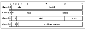
When a receiver joins a multicast group, its local CBT router looks up the multicast address and obtains the address of the Core router for the group. It then sends a Join message for the group toward the Core. At each router on the way to the Core, forwarding state is instantiated for the group, and an acknowledgment is sent back to the previous router. In this way, a multicast tree is built, as shown in Figure 2.
Figure 2:Formation of a CBT Bi-directional shared Tree
*Note:Click above for larger view
If a sender (that is, a group member) sends data to the group, the packets reach its local router, which forwards them to any of its neighbors that are on the multicast tree. Each router that receives a packet forwards it out of all its interfaces that are on the tree except the one the packet came from. The style of tree CBT builds is called a "bi-directional shared tree," because the routing state is "bi-directional"-packets can flow both up the tree toward the Core and down the tree away from the Core, depending on the location of the source, and packets are "shared" by all sources to the group. This scenario is in contrast to "unidirectional shared trees" built by PIM-SM as we shall see later.
IP multicast does not require senders to a group to be members of the group, so it is possible that a sender's local router is not on the tree. In this case, the packet is forwarded to the next hop toward the Core. Eventually the packet will either reach a router that is on the tree, or it will reach the Core, and it is then distributed along the multicast tree.
CBT also allows multiple Core routers to be specified, adding a little redundancy in case the Core becomes unreachable. CBT never properly solved the problem of how to map a group address to the address of a Core. In addition, good Core placement is a difficult problem. Without good Core placement, CBT trees can be quite inefficient, and so CBT is unlikely to be used as a global multicast routing protocol.
However, within a limited domain, CBT is very efficient in terms of the amount of state that routers need to keep. Only routers on the distribution tree for a group keep forwarding state for that group, and no router needs to keep information about any source; thus CBT scales much better than flood-and-prune protocols, especially for sparse groups where only a small proportion of subnetworks have members.
PIM Sparse-Mode
The work on CBT encouraged others to try to improve on its limitations while keeping the good properties of shared trees, and PIM Sparse- Mode [7] was one result. The equivalent of a CBT Core is called a Rendezvous Point (RP) in PIM, but it largely serves the same purpose.
When a sender starts sending, whether it is a member or not, its local router receives the packets and maps the group address to the address of the RP. It then encapsulates each packet in another IP packet (imagine putting one letter inside another, differently addressed, envelope) and sends it unicast directly to the RP.
When a receiver joins the group, its local router initiates a Join message that travels hop-by-hop to the RP instantiating forwarding state for the group. However, this state is unidirectional state-it can be used only by packets flowing from the RP toward the receiver, and not for packets flowing back up the tree toward the RP. Data from senders is de-encapsulated at the RP and flows down the shared tree to all the receivers.
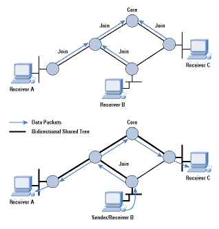
PIM-SM is an improvement on CBT in that discovery of senders and and tree building from senders to receivers are separate functions. Thus PIM-SM unidirectional trees are not particularly good distribution trees, but they do start data flowing to the receivers. Once this data is flowing, the local router of a receiver can then initiate a transfer from the shared tree to a shortest-path tree by sending a source-specific Join message toward the source, as shown in Figure 3. When data starts to arrive along the shortest-path tree, a prune message can be sent back up the shared tree toward the source to avoid getting the traffic twice.
Figure3: Formation of a PIM Sparse-Mode Tree
*Note:Click above for larger view
Unlike other shortest-path tree protocols such as DVMRP and PIM-DM, where prune state exists everywhere there are no receivers, with PIM-SM, source-specific state exists only on the shortest-path tree. Also, low-bandwidth sources such as those sending Real-Time Control Protocol (RTCP) receiver reports do not trigger the transfer to a shortest-path tree, a scenario that further helps scaling by eliminating unnecessary source-specific state.
Because PIM-SM can optimize its distribution trees after formation, it is less critically dependent on the RP location than CBT is on the Core location. Hence the primary requirement for choosing an RP is load balancing. To perform multicast-group-to-RP mapping, PIM-SM redistributes a list of candidates to be RPs to all routers. When a router needs to perform this mapping, it uses a special hash function to hash the group address into the list of candidate RPs to decide the actual RP to join.
Except in rare failure circumstances, all the routers within the domain will perform the same hash, and come up with the same choice of RP. The RP may or may not be in an optimal location, but this situation is offset by the ability to switch to a shortest-path tree.
The dependence on this hash function and the requirement to achieve convergence on a list of candidate RPs does, however, limit the scaling of PIM-SM. As a result, it is also best deployed within a domain, although the size of such a domain may be quite large.
Interdomain Multicast Routing
All the multicast routing schemes described so far suffer from scaling problems of one form or another:
- DVMRP and PIM-DM initially send data everywhere, and require routers to hold prune state to prevent this flooding from persisting.
- MOSPF requires all routers to know where all receivers are.
- PIM-SM needs redistribution of information about the set of RPs. Because traffic needs to flow to the RP, an RP cannot handle too many groups simultaneously, so many RPs are needed globally.
Thus each of these schemes is likely to be best deployed within a domain. How then does interdomain multicast routing take place? Long-term solutions to this problem will be discussed in the second of these articles. In the meantime, the interim solution currently being deployed consists of multiprotocol extensions to the unicast Border Gateway Protocol (BGP) interdomain routing protocol, and a protocol called MSDP to glue PIM-SM domains together.
Multiprotocol BGP
For either technical or policy reasons, not all routers or peerings between Internet Service Providers (ISPs) are multicast capable. This situation complicates the use of PIM-SM for operation between domains because PIM assumes that the route obtained by unicast routing is good for multicast routing (strictly speaking, PIM assumes the reverse unicast path is good for forward-path multicast routing). If, in fact, the reverse unicast path is not good for forward-path multicast, then Join messages will often reach routers that do not support multicast, resulting in a lack of multicast connectivity. How then do we solve this problem?
BGP is the unicast interdomain routing protocol that is very widely used to connect unicast routing domains together. The multiprotocol extensions to BGP allow multiple routing tables to be maintained for different protocols. Thus with the Multiprotocol Extensions for BGP-4 (MBGP) [2], you can build one routing table for unicast-capable routes and one for multicast-capable routes using the same protocol. PIM can then use the multicast-capable routes to forward Join messages and can, therefore, detour around parts of the network that don't support multicast.
Multicast Source Discovery Protocol
In addition to the problem of designing a scalable mechanism for mapping multicast groups to RPs, attempts to use PIM-SM as an interdomain protocol are hindered by ISPs' desire not to be dependent on other ISPs' facilities. For example, consider a multicast group consisting of senders and receivers in two domains, A and B, run by two different ISPs. If the RP is in domain A, and there is some problem in domain A, then senders and receivers in domain B might still be unable to communicate with each other using multicast, even though they are in the same domain, because initial PIM register messages must go via the RP. ISPs do not want to be dependent on other ISPs for connectivity within their own domain, so it appears that using PIM-SM as an interdomain protocol would be unacceptable, even if there were no scalability problems.
The Multicast Source Discovery Protocol (MSDP) [8] is an attempt to work around this problem. It does not provide a long-term scalable solution, but does provide a solution that solves the ISP interdependence problem.
With MSDP, ISPs run PIM-SM within their own domain, and they have their own set of RPs for all groups within that domain. Additionally, the RPs within the domain are interconnected with each other and with RPs in neighboring domains using MSDP control connections to form a loose mesh.
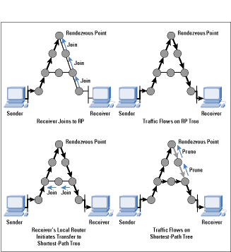
The process is shown in Figure 4. Within domain 1, R1 and R2 send Join messages from group G to RP-1. Similarly, R3 and R4 send Join messages to RP-2. When S starts sending, its packets are encapsulated to RP-2 by its local router in the normal PIM-SM manner. RP-2 decapsulates the packets and forwards them down the group-shared tree within domain 2 to reach R3 and R4. In addition, it sends a Source Active message over the MSDP mesh to all other RPs. RPs like RP-1 that have active joiners for this group then send a source-specific Join back across the interdomain boundary toward S. Traffic is then delivered interdomain following the source-specific state laid down by the Join messages, and it is eventually delivered to R1 and R2.
Figure 4: MSDP in Operation 
*Note:Click above for larger view
MSDP uses the normal PIM-SM source-specific join mechanism interdomain following the MBGP multicast routes back to the source, but it sets up only a group-shared tree within each domain, avoiding the need to depend on remote RPs in different domains for the delivery of traffic between local members in a domain.
As an interdomain routing protocol, however, MSDP has many shortcomings. In particular, every RP in every domain must be told about every source that starts sending, and a significant subset of the RPs must cache all this information so that receivers that join late can cause source-specific Joins to be sent by their local RP. Thus MSDP does not scale well if there are a large number of senders worldwide.
In addition, to ensure that the first few packets sent by a source do not get lost, they must be encapsulated and sent alongside the Source Active message to all the RPs that might possibly have receivers. If they are not encapsulated, then sources that send only a few packets every few minutes might never get any data through to receivers because the source-specific state has timed out after each time they send.
In summary, MSDP is not a scalable long-term solution to interdomain multicast routing. However, it does solve a real short-term problem faced by ISPs, and so it is currently seeing significant deployment.
Multicast Address Allocation
A local protocol for requesting multicast addresses from multicast address allocation servers has recently been standardized. This protocol is called Multicast Address Dynamic Client Allocation Protocol , or MAD-CAP [10]. It is a relatively simple request-response protocol loosely modeled after the Dynamic Host Configuration Protocol (DHCP) [6].
MADCAP is intended to be used with interdomain protocols that perform dynamic allocation of parts of the multicast address space between domains, but because these protocols are not yet deployed, they will be discussed in the second of these articles.
As an interim solution for interdomain address allocation, a simple static mechanism has been defined. This mechanism involves embedding the Autonomous System (AS) number of the domain as the middle 16 bits of a multicast address. Thus the domain with AS number 16007 would get multicast addresses in the range 233.64.7.0 to 233.64.7.255 (64 and 7 being the upper and lower bytes, respectively, of 16007). Known as glop addressing , this mechanism is experimental. It may be superseded by a dynamic mechanism in the longer term.
Multicast Scoping
When applications operate in the global Multicast backbone (MBone), it is clear that not all groups should have global scope. Not only is this constraint especially important for performance reasons with flood and prune multicast routing protocols, but it also is true with other routing protocols for application security reasons and because multicast addresses are a scarce resource. Being able to constrain the scope of a session allows the same multicast address to be in use at more than one place as long as the scopes of the sessions do not overlap. This is analogous to the same radio frequency being used by two radio stations operating far apart from one another-each will only be heard locally.
Multicast scoping can currently be performed in two ways, known as TTL Scoping and Administrative Scoping . Currently TTL scoping is most widely used, with only a very few sites making use of administrative scoping.
TTL Scoping
When an IP packet is sent, an IP header field called Time To Live (TTL) is set to a value between zero and 255. Every time a router forwards the packet, it decrements the TTL field in the packet header, and if the value reaches zero, the packet is dropped. The IP specification also states that the TTL should be decremented if a packet is queued for more than a certain amount of time, but this decrement is rarely implemented these days. With unicast, the TTL is normally set to a fixed value by the sending host (64 and 255 are commonly used) and is intended to prevent packets from looping forever.
With IP multicast, the TTL field can be used to constrain how far a multicast packet can travel across the MBone by carefully choosing the value put into packets as they are sent. However, because the relationship between hop count and suitable scope regions is poor at best, the basic TTL mechanism is supplemented by configured thresholds on multicast tunnels and multicast-capable links. Where such a threshold is configured, the router will decrement the TTL, as with unicast packets, but then will drop the packet if the TTL is less than the configured threshold. When these thresholds are chosen consistently at all of the borders to a region, they allow a host within that region to send traffic with a TTL less than the threshold, and to know that the traffic will not escape that region.
An example is the multicast tunnels and links to and from Europe, which are all configured with a TTL threshold of 64. Any site within Europe that wishes to send traffic that does not escape Europe can send with a TTL of less than 64 and be sure that its traffic does not escape. However, there are also likely to be thresholds configured within a particular scope zone-for example, most European countries use a threshold of 48 on international links within Europe, and because TTL is still decremented each time the packet is forwarded, it is good practice to send European traffic with a TTL of 63, a scenario that allows the packet to travel 15 hops before it would fail to cross a European international link.
Administrative Scoping
In some circumstances it is difficult to consistently choose TTL thresholds to perform the desired scoping. In particular, it is impossible to configure overlapping scope regions as shown in Figure 5, and TTL scoping has numerous other problems, so more recently, administrative scoping has been added to the multicast forwarding code in mrouted and in most router implementations.
Figure 5: Overlapping Scope Zones possible with Administrative Scoping
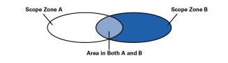
*Note:Click above for larger view
Administrative scoping allows the configuration of a boundary by specifying a range of multicast addresses that will not be forwarded across that boundary in either direction.
Scoping Deployment
Administrative scoping is much more flexible than TTL scoping, but it has many disadvantages. In particular, it is not possible to tell from the address of a packet where it will go unless all the scope zones that the sender is within are known. Also, because administrative boundaries are bi-directional, one scope zone nested within or overlapping another must have totally separate address ranges. This makes address allocation difficult from an administrative point of view, because the ranges ought to be allocated on a top-down basis (largest zone first) in a network where there is no appropriate top-level allocation authority. Finally, it is easy to misconfigure a boundary by omitting or incorrectly configuring one of the routers. With TTL scoping it is likely that in many cases a more distant threshold will perform a similar task, lessening the consequences, but with administrative scoping, there is less likelihood that this scenario will occur.
For these reasons, administrative scoping has been viewed by many network administrators as a specialty solution to difficult configuration problems, rather than as a replacement for TTL scoping, and the Mbone still very much relies on TTL scoping. However, this situation is set to change as a protocol for automatically discovering scope zones (and scope zone misconfigurations) starts to be deployed. This protocol is called the Multicast Zone Announcement Protocol (MZAP) [9], and it will shortly become an IETF Proposed Standard. Eventually the use of configured TTL scopes to restrict traffic will cease to be used as a primary scoping mechanism.
Summary
In this article we have looked at the various routing systems that are used to devise delivery trees over which multimedia data can be sent for the purposes of group communication, and at address allocation and scoping mechanisms for this traffic.
After ten years of experimentation, IP multicast is not currently a ubiquitous service on the public Internet, but significant deployment has taken place on private intranets. The existing multicast routing and address allocation mechanisms work well at the scale of domains. However, as we have seen, there are still significant technical problems concerning scaling to be overcome before multicast can be a ubiquitous interdomain service. In addition to the routing problems, we also still lack deployed congestion control mechanisms for multicast traffic, which are essential if multicast applications are to be safely deployed.
Despite these issues, IP multicast still shows great promise for many applications. Solutions have been devised to many of the remaining problems, although they have not yet been deployed. In the second of these articles, we will look at the proposed solutions for scalable interdomain routing and address allocation. We will also touch on multicast congestion control and the solutions that are currently emerging from the research community.
Document Status
A list of IETF specifications for the protocols discussed in this article is given below. We include the status for each document as of this writing (November 1999). For more information, check the IETF Web pages at www.ietf.org
References
- Ballardie, A., "Core Based Trees (CBT version 2) Multicast Routing," RFC 2189, September 1997.
- Bates, T., Chandra, R., Katz, D., and Rekhter, Y., "Multiprotocol Extensions for BGP-4," RFC 2283, February 1998.
- Deering, S., "Host Extensions for IP Multicasting," RFC 1112, August 1989.
- Deering, S., Partridge, C., and Waitzman, D., "Distance Vector Multicast Routing Protocol," RFC 1075, November 1988.
- Deering, S., Estrin, D., Farinacci, D., Jacobson, V., Helmy, A., Meyer, D., and Wei, L., "Protocol Independent Multicast Version 2 Dense Mode Specification," Internet Draft, work in progress.
- Droms, R., "Dynamic Host Configuration Protocol," RFC 1531, October 1993.
- Estrin, D., Farinacci, D., Helmy, A., Thaler, D., Deering, S., Handley, M., Jacobson, V., Liu, C., Sharma, P., and Wei, L., "Protocol Independent Multicast-Sparse Mode (PIM-SM): Protocol Specification," RFC 2362, June 1998.
- Farinacci D. et al. "Multicast Source Discovery Protocol (MSDP)," Internet Draft, work in progress, June 1998.
- Handley, M., Thaler, D., and Kermode, R., "Multicast-Scope Zone Announcement Protocol (MZAP)," Internet Draft, work in progress.
- Hanna, S., Patel, M., and Shah, M., "Multicast Address Dynamic Client Allocation Protocol (MADCAP)," RFC 2730, December 1999.
- Moy, J., "OSPF Version 2," RFC 2328, April 1998.
- Moy, J., "Multicast Extensions to OSPF," RFC 1584, March 1994.
- Miller, C. K., "Reliable Multicast Protocols and Applications," The Internet Protocol Journal , Volume 1, No. 2, September 1998.
JON CROWCROFT is a professor of networked systems in the Department of Computer Science, University College London, where he is responsible for a number of European and U.S. funded research projects in Multimedia Communications. He has been working in these areas for over 18 years. He graduated in Physics from Trinity College, Cambridge University, in 1979, and gained his MSc in Computing in 1981, and PhD in 1993. He is a member of the ACM, the British Computer Society, and is a Fellow of the IEE and a senior member of the IEEE. He is a member of the Internet Architecture Board (IAB) and was general chair for the ACM SIGCOMM from 1995 to 1999. He is also on the editorial team for the ACM/IEEE Transactions on Networks. With Mark Handley, he is the co-author of WWW: Beneath the Surf (UCL Press); he also authored Open Distributed Systems (UCL Press/Artech House), and with Mark Handley and Ian Wakeman, a third book, Internetworking Multimedia (Morgan Kaufmann Publishers), published in October 1999.
E-mail: J.Crowcroft@cs.ucl.ac.uk
MARK HANDLEY received his BSc in Computer Science with Electrical Engineering from University College London in 1988 and his PhD from UCL in 1997. For his PhD he studied multicast-based multimedia conferencing systems, and was technical director of the European Union funded MICE and MERCI multimedia conferencing projects. After two years working for the University of Southern California's Information Sciences Institute,he moved to Berkeley to join the new AT&T Center for Internet Research at ICSI (ACIRI). Most of his work is in the areas of scalable multimedia conferencing systems, reliable multicast protocols, multicast routing and address allocation, and network simulation and visualization. He is co-chair of the IETF Multiparty Multimedia Session Control working group and the IRTF Reliable Multicast Research Group. E-mail: mjh@aciri.org
[This article is based in part on material in Internetworking Multimedia by Jon Crowcroft, Mark Handley, and Ian Wakeman, ISBN 1-55860-584-3, published by Morgan Kaufmann in 1999. Used with permission]. |
|


